
A team day presentation asked for a five-minute talk on any subject, and I used mine to justify something I’d been meaning to do for years: build a Game Boy emulator from scratch. The research for five minutes of slides turned into an ongoing project, a fully functional Game Boy emulator written in Go, and this post is the long version of that talk.
The slides1 were little more than prompts. What they skipped over is the thing worth writing down: how much engineering depth hides beneath the surface of a machine most people remember as a simple grey brick.
Which Game Boy? Link to heading
“Game Boy” isn’t one device. It’s a lineage spanning three distinct hardware platforms. First came the original 8-bit platform, which includes the iconic 1989 Dot Matrix Game (DMG). Next was the Game Boy Color, a significant but incremental upgrade that added colour and a bit more power whilst maintaining backward compatibility. Finally, the Game Boy Advance arrived as a completely new ARM-based architecture, a powerful successor that could play older games but whose own games were entirely incompatible with the original hardware.
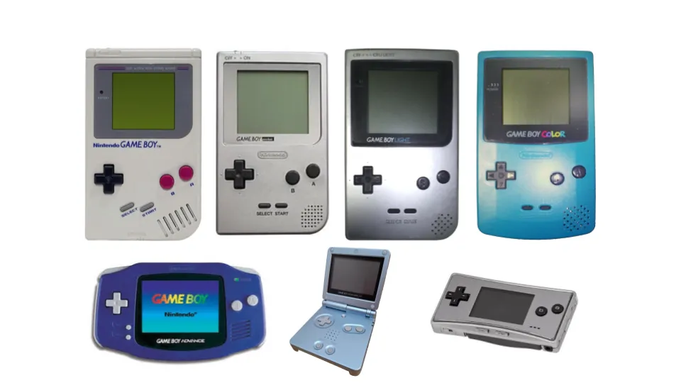
This post focuses on the original 8-bit architecture (top row of the above image). It’s the foundation for both the classic Game Boy and the Game Boy Color, and the traditional starting point for any emulator developer.
The device looked underpowered at launch. It faced full-colour, backlit handhelds like the Atari Lynx and Sega Game Gear, and chose a monochrome screen anyway. That trade-off is why it won. The Lynx and Game Gear drained their batteries in 3 to 5 hours; the Game Boy ran for 15 to 30. Longevity beat flair, and Nintendo owned the handheld market for decades off the back of it. The chip at the centre of that decision is where the engineering gets interesting.
The Sharp LR35902 CPU Link to heading
The Sharp LR35902 is a custom processor with a mongrel heritage and a set of pragmatic compromises that shape everything about how the Game Boy behaves.
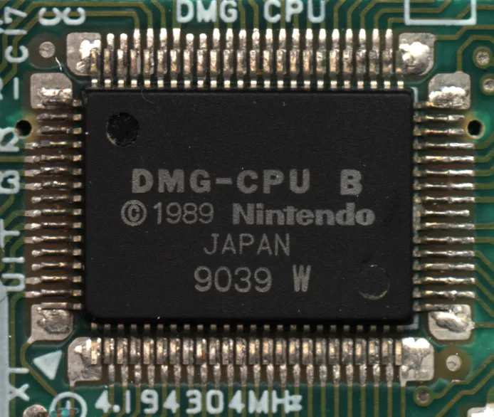
It’s a System on a Chip (SoC): a single piece of silicon integrating the CPU core, graphics (PPU), sound controller and I/O. That kept costs down, in contrast to consoles like the SNES that spread the same work across multiple dedicated chips.
The characteristics that matter for emulation:
A Hybrid Heritage: Many documents, including my original presentation slides mischaracterise or over-simplify the chip as being essentially a stripped-down Zilog Z80 (of ZX Spectrum, Sega Master System & Pacman Arcade Cabinet fame). The reality is more interesting: the LR35902 is a custom hybrid. It inherits its core register set and instruction encoding from the venerable Intel 8080, but borrows a handful of powerful bit manipulation instructions from the Z80, leaving the rest of the Z80’s complexity behind.
The 4 MHz vs. 1 MHz Debate: The CPU’s clock crystal runs at 4.19 MHz. However, the system is fundamentally memory-bound; the CPU can only calculate as fast as it can access data from RAM. Since the memory bus runs at 1 MHz and most operations require memory access, the entire system is effectively paced at 1 million “machine cycles” per second. Thinking of it this way makes its performance much more comparable to other 1 MHz systems of the era, like the Nintendo Entertainment System.
Key Features: The CPU has a 16-bit address bus, allowing it to access up to 64KB of memory. Its design is incredibly power-efficient, a major contributor to the console’s legendary battery life. As a pragmatic choice for a simpler, more cost-effective chip, it lacks any dedicated hardware instructions for multiplication or division; these operations had to be performed in software.
Registers Link to heading
Registers are a small set of storage locations built directly into the CPU, far faster to reach than main RAM. The CPU keeps the values it’s actively working on here instead of fetching them from memory every time.
For an 8-bit chip, the LR35902’s register set is small and easy to hold in your head:
General Purpose Registers Link to heading
The workhorses of the CPU are a set of 8-bit registers that can also be cleverly paired up to function as 16-bit registers, perfect for holding memory addresses.
| 15 … 8 | 7 … 0 |
|---|---|
| A (Accumulator) | F (Flags) |
| B | C |
| D | E |
| H | L |
The A register, or Accumulator, is special. It’s the primary register used for almost all arithmetic and logical operations.
Special Purpose Registers Link to heading
Two 16-bit registers handle the program’s flow.
| 15 … 0 |
|---|
| SP (Stack pointer) |
| PC (Program counter) |
- SP (Stack Pointer): Keeps track of a special area in memory called the stack, which is used for temporarily storing data, like the return address when a function is called.
- PC (Program Counter): This is one of the most important registers, as it always holds the memory address of the next instruction the CPU is supposed to execute.
The Flags Register Link to heading
The F register is unique. Its individual bits (or “flags”) are used to track the outcome of the most recent operation.
| 7 | 6 | 5 | 4 | 3 | 2 | 1 | 0 |
|---|---|---|---|---|---|---|---|
| Z | N | H | C | 0 | 0 | 0 | 0 |
Note that the lower four bits are unused and always read as zero.
- Z - Zero Flag: Think of this as a light that turns on whenever the result of a math operation is exactly zero. This is crucial for checking if two values are equal (by subtracting them).
- N - Subtract Flag: This flag simply notes whether the last operation was a subtraction.
- H - Half Carry Flag: This is a specialized flag used for handling complex internal math. While crucial for certain low-level operations, it’s less commonly used in day-to-day game logic.
- C - Carry Flag: This turns on if an operation results in a value too large to fit in the register, like adding 1 to 255 in an 8-bit register. It’s also used to signal a “borrow” in subtraction.
Instructions and Interrupts Link to heading
The instruction set is the complete vocabulary of commands the CPU understands, from arithmetic (ADD, SUBTRACT) and logic (AND, OR) to memory operations (LOAD, STORE) and flow control (JUMP, CALL). The full opcode table has the detail.2
Just as important as the instruction set is the concept of interrupts. An interrupt is a signal from hardware that tells the CPU to immediately pause what it’s doing and handle a more urgent task. Think of it like a doorbell ringing while you’re reading a book. You put a bookmark where you are (the CPU saves its state), answer the door (the CPU runs special “interrupt handler” code), and then return to your book right where you left off. This mechanism is critical for a game console, allowing it to respond to real-time events.
The Game Boy has five hardware sources that can trigger an interrupt:
- VBlank: Triggered when the screen has finished drawing a full frame. This provides a “vertical blanking” interval - a safe, quiet moment for the game to update graphics data without causing visual tearing.
- LCDC: Triggered by the LCD controller for various screen-related status updates, allowing for more advanced graphical effects.
- Timer: Triggered by a configurable internal clock. This is perfect for timing events in the game, independent of how fast the main code is running.
- Serial: This is the lifeline for multiplayer gaming, firing every time a piece of data arrives from a friend’s console via the Link Cable.
- Joypad: Triggered the moment a player presses a button. This allows the game to react instantly, rather than wasting precious cycles constantly asking the system, “Is a button pressed now? How about now?”
Hello World? Link to heading
A real “Hello World” that prints to the screen drags in the entire graphics subsystem, far too much for a quick example. A three-instruction program shows how registers, memory and opcodes work together without that baggage.
LD A, $41       ; Load ASCII 'A' into register A
LD (0xC000), A  ; Store it in memory
HALT
What each step does:
LD A, $41: load the hexadecimal value $41 (ASCII for ‘A’) into the 8-bit Accumulator (A).LD (0xC000), A: the parentheses mean “the memory address of”, so this stores whatever is in the Accumulator at address 0xC000, inside the Game Boy’s 8KB of internal work RAM (WRAM).HALT: stop fetching and executing instructions until an interrupt occurs.
Three steps: a value into a register, then out to RAM. Every game from Tetris to Pokémon is built from primitives this small. The simplicity is real, and so is the complexity hiding behind it.
The Rabbit Hole Link to heading
The official manuals3 tell you how the Game Boy is supposed to work. The emulator project is where I learned how it actually works, which is a different thing entirely.
Reverse engineer Joonas Javanainen made the point well in his Disobey 2018 talk4: there are around 20 hardware revisions of the Game Boy CPU alone, each with subtle undocumented differences in behaviour. These matter. Pinball Deluxe runs perfectly on real hardware and crashes on most emulators, because its code leans on an undocumented timing quirk that only hardware-accurate emulation reproduces. Chasing down behaviour like that is most of the real work in writing an emulator, and most of the fun.
The machine dismissed as a simple retro toy is a lesson in getting a lot out of very little. I’m nowhere near done with the Go emulator, and every timing nuance and hardware oddity I turn up makes the next one more interesting. This won’t be the last post on the subject.